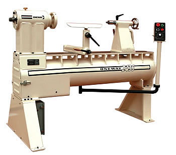
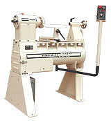
2436, 2416, 2036, 2016 Lathes
Specifications Overview
- Spindle taper - #2 Morse
- Tailstock taper - #3 Morse
- Spindle thread - M33 * 3.5 RH (inboard and outboard, making attachments quickly interchangeable.)
- Optional spindle heights are available (at no extra charge):
20" models: 41", 42", 44", and 46"
24" models: 43", 44", 46", and 48" - Outboard attachments are available in two sizes
- Two bed extensions are available - 17" extension & 60" extension. Extensions bolt on to the end of the bed allowing the turner an extended distance between centers.
The table below provides a brief overview of our four models, and capacities which pertain to that particular model of machine :
|
Model |
Swing |
Between Centers |
Total Length |
Weight |
2436 |
24" |
36" |
60" |
850 lbs |
2416 |
24" |
16" |
40" |
650 lbs |
2036 |
20" |
36" |
60" |
800 lbs |
2016 |
20" |
16" |
40" |
600 lbs |
For a more detailed Specifications page, click here.
 Headstock
- Features a four bearing spindle
At the front are two 45 mm internal diameter ball bearings custom fitted with ground spacers, and locked to the shaft with a clamp ring and lock nut. This minimizes radial and axial play of the spindle. The 40 mm diameter rear bearings float axially to allow for heat expansion. Bearings are no maintenance greased for life. - Six position spindle lock and 7-1/2û (48 position) indexing is standard.
- The spindle is 50 mm (2 inches) at maximum diameter, 16" long and bored 5/8" diameter through with number 2 morse taper at the inboard end. It is made from high alloy steel, hardened and ground to precision tolerance of ±0.0003 thousands of an inch.
The Spindle
- The spindle nose, which holds the front bearings, protrudes approximately 3" in front of the headstock allowing easy tool maneuvering when working on the backside of a plate or bowl.
- The thread is M33 * 3.5 with a groove machined for a lock screw to allow full power forward and reverse turning. This design contributes to the safety of this machine, as it eliminates the possibility of chucks or face plates accidentally unscrewing from the spindle.
- The spindle is the cartridge type and can be pulled fully assembled from the headstock by removing six bolts. If a belt ever needs to be changed, it should take less than ten minutes by even the most novice mechanic.
- Pulley Size: 3 step 10 groove Poly V
The Tailstock
- Barrel & Leadscrew
Both the Barrel & the Lead Screw are manufactured from high strength steel. This steel has tensile strength of over 110,000 lbs per square inch. That's twice as strong as standard 1020 steel. - Casting
The casting is ductile, and is designed to bend before it will break. - Other Features:
- The tailstock has an 1-1/2" diameter quill with 4" travel.
- The lead screw is a 3/4" diameter 6 pitch acme thread and the barrel has a 3-1/2" bearing length.
- The 5" handwheel and the high lead on this screw allows rapid in and out feeds for drilling.
- Precision design and a No. 3 Morse Taper allows the use of stronger live centers and larger drills.
- Super rigid tailstock clamp is designed so that no flexing will occur under clamp pressure. This will ensure that the clamp will hold firmly while requiring no adjustment for the life of the lathe, and will retain the ease of movement of the tailstock along the bed.
- The through hole is 5/16" (8 mm) diameter which allows lamp base and similar drilling to be carried out.
- The tailstock is handled for easy removal and adjustments.
The Banjo / Toolrest Base
The BANJO/TOOLREST BASE is a radical new design that assures even, powerful locking anywhere on the bed (PATENT No. 6000447). The sliding cam is supported by a cam support block which rests on a ledge machined in the toolrest base.
Note: Our Toolrest Base is available as an aftermarket item to upgrade your flatbed lathe. Click here for more details.
Banjo/ Toolrest Base Design
The patented ONEWAY toolrest base is designed to solve problems associated with traditional camlock toolrest bases. This sliding cam clamping mechanism ensures tight clamping and smooth operation in every position on the lathe bed.
What makes our Banjo's clamping mechanism better than conventional methods?
Conventional long cam shafts suffer from cam shaft deflection. This causes non-uniform clamping over the range of the toolrest base. Cam shaft deflection causes a related problem - the clamp handle tightens in a different position when the toolrest base is moved from front to back.
This conventional clamping mechanism consists of a cam shaft that runs the entire length of the toolrest base. Deflection is unavoidable using this unsupported system. Deflection occurs because the cam shaft is so long, it bends when clamping pressure is applied when positioned in the middle.
ONEWAY has solved this problem by replacing the regular long shaft cam with a sliding cam assembly.
What is a sliding cam assembly?
This assembly consists of a rotating square shaft, a short sliding cam and a support block for the sliding cam. The square shaft rotates the sliding cam. The cam is supported on a cam support block which in turn is supported on a ledge machined in the tool rest base. The block moves with the sliding cam and supports the shaft. Deflection of the cam shaft is eliminated and there is no longer a clamping difference anywhere on the lathe bed. When unclamped the handle is always at the 12 o'clock position and clamping may be adjusted to be repeatable anywhere between 10 & 6 o'clock with RH and LH clamping always at the same angle.
Can I purchase a Banjo for my flatbed lathe?
The toolrest base was originally designed for ONEWAY Lathes, but because it is a significant improvement over current designs, we are offering the toolrest base and toolrest as upgrades to replace existing banjo/toolrests for flatbed lathes.
If you have a flatbed lathe, and you find your toolrest does not clamp sufficiently or slide smoothly, you can solve the problem with ONEWAY's new toolrest base.
The Toolrest
The toolrest is clamped in the banjo with a captured non-marking block. As a result a very tight fitting hole can be bored, improving the toolrest clamp position. The clamp screw handle may (used to lock the toolrest into place) can be adjusted at 45 degree rotations to ensure minimum interference when turning.
Toolrest Features:
- The toolrest is designed to work with the banjo so that you can get very close to the front and back side of turnings.
- Made from ductile iron, it is stronger than cast iron and will last longer.
- It is suitable for underhanded and overhanded grips.
Can these Toolrests be used with other lathes?
Yes. As long as your toolrest base has a 1" hole, our toolrest will work.
Note: Please check our Toolrest Page for specific details.
The Drive / Inverter
The electronics contained in all our lathes are of the highest quality. We invested a lot of time and effort to find an inverter which would be extremely reliable, yet flexible enough to suit our needs. These Inverters are the very best we could find.
- Our inverters are AC electronic variable speed with ramp up/ramp down, forward/reverse, and dynamic braking.
- 220 volt, Single Phase AC
- A 9 foot power cord with a 15 Amp plug is standard.
- Our Inverters are pre-programed ready for use.
- The drive package is fully electronic with speeds from 0 - 3000 RPM (forward or reverse).
- Lathes are available in 1.5 HP, 2 HP, and 3 HP packages.
- Excellent torque is available at as low as 30 RPM, with brute force available at as little as 100 RPM.
- Speed ranges are 70-700 / 190-1900 / 305-3050. Changing range is easy and can be completed in under one minute.
- Controls for this drive are mounted on a swinging pendant which can be moved to the headstock or tailstock for easy reach and clearance at all times.
What are the power requirements?
The AC variable speed drive we use on the lathe changes the requirements a bit compared to a normal AC motor. If you plug in a AC electric motor, it draws the amps that are on the name plate continuously. This gives the wiring in the circuit time to heat up and possibly even melt.
The AC variable speed drives that we use have power optimization circuitry, they only let through the power that is required. While the lathe is just spinning the wood, only 2 or 3 Amps is required. When you are cutting it will let through up to 150% of the motor capacity for up to one minute.
One minute might not sound like a long time, but when was the last time you took a very heavy roughing cut that lasted over one minute?
The maximum that the drive will let through as a very short term surge, is even greater. I have seen them go up to 200% while testing. So if you take a short heavy cut the lathe will do its best to accomodate you. The time it will allow you to do this is so brief, that wires and insulation do not have enough time to heat up, but there is enough there to blow a small breaker.
If you put in a 15 Amp breaker, you will get what we call "nuisance tripping". This is why we recommend a minimum of a 20 Amp breaker (see below).
Note: Also please keep in mind that the drive takes care of electricity that comes out of it. It will shut down if there is a short circuit on the motor side of the wiring. The breaker on the wall is there strictly to protect you.
- Breaker Recommendations
1½ HP Drive - use a 20 Amp Breaker
2 & 3 HP Drives - use a 25 Amp Breaker
The Bed
- Bedways and ribs are welded to a 10-3/4 inch diameter * 5/16 inch wall tube. The assembly is stress relieved and precision machined.
- Almost perfect torsional rigidity is achieved - many times more so
than twin tube or cast iron bed designs.
| Quicklinks: Lathes, Lathe Accessories | ||
| » 2436 | » 1640 | » 1224 |
Pricing
Model Number |
Horse- Power (HP) |
Price |
2436 |
1,5 |
€5606,34 |
2436 |
2 |
€5852,54 |
2436 |
3 |
€6154,14 |
2416 |
1,5 |
€5472,98 |
2416 |
2 |
€5719,18 |
2416 |
3 |
€6020,78 |
2036* |
1,5 |
€5288,32 |
2036* |
2 |
€5534,52 |
2036* |
3 |
€5836,13 |
2016* |
1,5 |
€5154,96 |
2016* |
2 |
€5401,16 |
2016* |
3 |
€5702,77 |
* These lathes are special order and will take a longer amount of time for delivery.
Included with your Lathe:
- 6" Faceplate
- #3 MT Live Center
- #2 MT Safe Driver
- 14" Toolrest
- Knock-out Rod
- Owners Manual
Shipping Details
Please call for an approximate shipping date and freight cost.
Product Reviews
- 2036 Review
by John McAtee
Customer Endoresments
Dear Sirs:
I wish to compliment you on the excellent engineering design and quality of your products. I have had the 2436 with both the extension and large headstock extension for four years and i am very happy with it and the thought that went into it. I would also note that I taught basic engineering at Purdue University for three years and during my career was the project manager for the design and construction of two nuclear plants - so i appreciate a great design, good excecution, and the mass and strength of material used in your work.
Sincerely yours,
James L. McAnally
Walnut Valley Wooworks
Manufacturers Warranty
All Oneway Lathes are backed by a warranty period of 5 years from the date of purchase. Non-manufactured parts (i.e. Drive, Motor, Bearings etc) are not covered under this warranty; please refer to the relevant Warranty information provided with the lathe.
Request for Quote
Fill out this form with the appropriate information and fax it to us at 1.519.271.8892. We will fax you back the quote including approximate shipping costs.
DOWNLOAD QUOTE FORM (145k)
(PDF Format)
Quick Links
|
» |
Headstock & Spindle |
|
» |
Tailstock |
|
» |
Banjo (Toolrest Base) & Toolrest |
|
» |
Drive (Inverter) |
»
|
Bed |
» |
Accessories |
Quick Reference Specifications
| » | Spindle Taper | #2 Morse |
| » | Tailstock Taper | #3 Morse |
| » | Spindle Thread (inboard) |
M33x3.5 Right Hand |
| » | Spindle Thread (outboard) |
M33 x 3.5 Right Hand |
| » | Spindle Bearings | Four (two front / two rear) - greased for life |
| » | Indexing | 48 position |
| » | Inverter | AC variable speed with ramp up/down & dynamic braking |
| » | Supply | 220 Volt, AC, Single Phase |
| » | Breaker Requirements: 1½ HP 2 & 3 HP |
20 Amp 25 Amp |
| » | Is the Inverter programmable? | Yes |
| » | Motor | Constant Torque |
| » | Speed Range | 70 - 700 / 190 - 1900 / 305 - 3000 |
| » | Tailstock Quill | 4" travel |
| » | Banjo Clamping Mechanism | Cam Lock (patented) |
| » | Vacuum Ready | Yes |
| » | Forward / Reverse | Standard |
| » | Emergency Stop | Standard |
| » | Hardened Spindle | Standard |
| » | Spindle Safety Groove | Standard |
| » | Spindle Lock | Standard |
Powder Paint
We now powder paint all our lathes. Advantages of this process over traditional painting methods include:
- increased scratch resistance
- easier to clean
- more environmentally friendly - no chemical waste normally associated with traditional painting methods
To view a Data Sheet specific to the powder paint we use on our lathes and lathe accessories, please click here.
Customization Options
We were not satisfied with just meeting capacity turning requirements, we wanted to make the lathe fit you. To that end we have made available four different spindle heights and three different horse power packages. All of these options are suitable and available for all four models of this lathe. If you purchase a lathe from us it should meet your needs right out of the crate.
IMPORTANT
The following accessories should be seriously considered when placing your lathe order as they are difficult or expensive to add later:
Do you have accessories you want to use on your 2436 Lathe?
If you have a large investment in accessories for your present lathe, a spindle adaptor is available which may adapt your spindle to the ONEWAY spindle size. Click here for more information.